“For us engineers we don't get paid to do things right,
we get paid to do things just right enough.”
- Adam Diedrich Steltzner
Many of the first products I designed required extensive analog, RF, and even digital circuit designs, rather than feature-rich OTS solutions, due to our low volumes and already high production costs associated with breaking into a new market. Naturally, as the business grew, so too did our ability to incorporate more complex capabilities such digital filtering (DSPs), high performance PLLs, COG/COM modules, higher performance microcontrollers and microprocessors, better software, and so much more. In addition to the product design, I also designed our own test and verification equipment, as well as test procedures. This was a critical function given that our products were designed to operate in extreme environmental conditions.
Below is a limited sample of some of the products I have designed during my career. While I developed both the firmware (or software) and hardware for each of these projects, this page is meant to provide examples of the analog and digital circuit design, as well my capabilities in PCB layout and construction.
2006 - PCAS XRX Project
One of the most challenging designs I encountered was designing the XRX in the PCAS line of collision avoidance systems. At the heart of its capabilities was the ability to detect the direction of arrival from other surrounding aircraft’s secondary surveillance RADAR, commonly referred to as the transponder signal. The design requirements, specified by our customers, included; A total package size of under 400 cm³, battery powered option, a direction of arrival of 22.5° ±11.25°, track multiple threats, and the ability select between an on-board display or to export our data to third-party GPS maps via a WiFi server, Bluetooth connection, RS232, and ARINC 429.

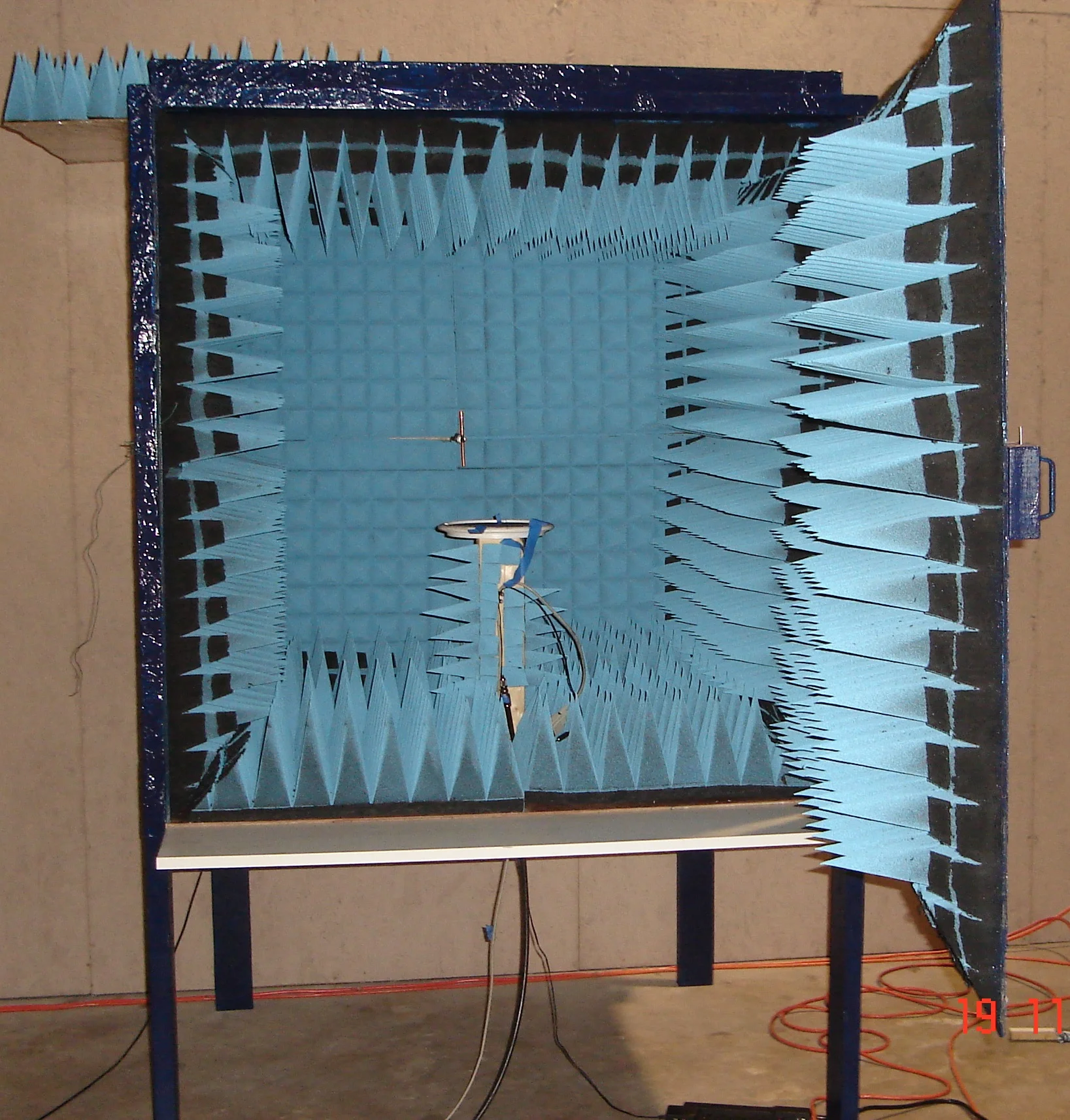
By far, the most difficult element in the design was the antenna. No other company had produced a directional antenna capable of such a feature, but after nearly a year and a half of persistence and dedication, I had finally produced a solution that not only exceeded expectations, but also had a bandwidth wide enough to streamline production without the need for physical tuning of each antenna element, but rather through software adjustments. To fine-tune each device during production, I designed my own anechoic chamber. Finally, with three-dimensional data such as, range, relative altitude, and now azimuth, our integration partners could easily display our data in a familiar format for pilots. In 2007 with the release of the PCAS XRX, we became the first avionics manufacturer to produce a portable, 3-dimensional, collision avoidance system for aerial vehicles.
As mentioned above, a large portion of the challenge during the XRX design was the directional antenna design. However, the second part to that challenge was to be capable of mass producing each device. To accurately tune and adjust each device’s directional antenna, I designed a custom anechoic chamber. The chamber not only allowed each of the four antennas to be adjusted based on the arriving signal by rotating the entire device, it also allowed sensors, such as the on-board digital compass, to be calibrated in tandem with the system to ensure the directional information could always remain relative to the nose of the pilot’s aircraft. The level of production testing had to be precise, however, with the addition of the chamber and other custom-built test equipment I created, it was possible for us to hire technicians to handle the daily production cycle with great efficiency.
2009 - xrxi installed system and MFD display
As a portable system, the XRX was a tremendous success bringing a large following of dedicated customers. Listening to their feedback, it wasn't long before several asked for an permanently installed version. The goal in the XRXi was two-fold; First, to use the existing and well-tested design of the XRX motherboard and antenna design, and second, to create a multi-function display (MFD) for a standard circular instrument panel slot.
Another advantage of the XRXi system was the ability to introduce antenna diversity. As can be seen in the photo on the right, the main XRX system (shown at the bottom) included coaxial connectors for both a top and a bottom antenna. This configuration allowed the XRXi to scan both above and top antennas to reduce shadowing from the aircraft fuselage. Two additional coaxial cable connectors were included to add a passive, host transponder sense input and a DC biased, GPS antenna input for ADS-b data correlation planned for future upgrade options.


The ability to mount the XRX antenna on the aircraft presented a unique opportunity as most aircraft are constructed from light-weight aviation grade aluminum which acted as a phenomenal groundplane for the directional antenna. With the vast improvement in groundplane, the antenna was again modeled, and the results yielded an azimuth accuracy of better than ±5 degrees. To protect the antenna, we contracted with an aircraft antenna manufacturer to produce a miniature radome to fit the directional antenna.

For the MFD design, a 480p color TFT display with a custom-designed graphics library and standard ARINC-429 interface for not only our systems, but to allow for future product expansion. The menu-driven display, interface circuits, graphic controller, and processor design required many layers of testing. Test and verification required the most amount of time as the software had to meet or exceed typical failure analysis parameters. Unlike all other projects, beta testing was conducted by volunteer customers rather than myself. During this period, I worked with the volunteers on technical aspects including constructing an installation guide and assisting their mechanics with various other specifications including power, antenna placement, and many other facets.

2012 - MX1090 Portable ADS-B System
After filing a patent for a portable ADS-b system, in 2012 it was granted. The first of several designs planned included the MX1090 with a mission to bridge the FAA's new technology, ADS-b, with proprietary data produced by the PCAS XRX. At the heart of ADS-b technology is the GPS receiver and a receiver for obtaining target aircraft messages. The MX1090 received messages directly from surrounding aircraft with each message containing the location which is then compared to the MX1090’s own on-board GPS location. This basic concept is the basis for ADS-b and the data collected was then correlated with data from a PCAS XRX to avoid overlapping false positives.
One critical design characteristic of the MX1090 was size. To minimize the overall size, a high-density pcb was used, however, the addition of the DSP processor and WiFi or Bluetooth option, in close proximity to the GPS and ADS-b receivers, required careful attention to noise and spurious emissions from the multitude of RF systems being utilized by the MX1090. To accomplish this, both the GPS and networking modules were located on a second daughter board from the processor to allow for better filtering, isolation, and ultimately better EMI control.

1. MX1090 2. MX1090 main pcb with GPS/Network daughter board 3. 1090 MHz ADS-b receiver 4. Daughter board GPS, LNA, and chip antenna
While a plethora of single-chip solutions exist for common RF applications, they rarely exist at the frequency range, price point, or volume appropriate for aviation applications. Therefore, designing RF transmitters or receivers must usually be accomplished using more discrete components and reduced-function integrated circuits such as individual PLLs, mixers, filters, LNAs, IF amplifiers, and demodulation techniques. As such, more testing is required to not only ensure functionality, but also compliance with high safety standards expected in the aviation marketplace. The MX1090 was no exception to this niche-phenomenon.

In addition to maintaining strict control over noise for maximum GPS performance, the ADS-b receiver also required an extremely low noise environment. This was accomplished by designing a custom, lumped element, Gaussian 70 MHz IF filter. By designing a custom IF filter, not only did it reduce costs and virtually eliminate typically long lead times, but a smooth group delay and high bandwidth could be maintained while allowing complete control over the attenuation of system-wide intermodulation products. Further filtering was performed using the DSP engine and the built-in cyclic redundancy check hardware feature on the DSP, enabled independent detection and back-end correction of the ADS-b and Mode-S messages received. Another key parameter required of the MX1090 was a low power consumption - no more than 1/2 watt in total. The typical general aviation aircraft power bus has an output ranging between 12-36 VDC which was converted to the MX1090's main supply voltage of 3.3 VDC using a discontinuous mode Buck converter. Lastly, serial communications, used to supply wire-based partners with data, included two full duplex RS-232 ports which were also configurable to facilitate production testing subroutines.
2017 - 802.11 WiFi Mesh Network ExteNDERS (using Arial DroneS)
As part of a sponsored Mozilla academic contest, I worked with other several engineers to create a proof-of-concept mesh networking system. The objectives I received consisted of designing the main pcb with a WiFi system (capable of supporting both the mesh network server and the access point network), a suitable ARM processor, and various hardware and software sub-components. Additionally, I was tasked with implementing an embedded Linux distribution with a Debian root file system to host the mesh network application (running OLSR on OpenWRT) designed by another team engineer (Chris Tsongas). The board sub-components included the necessary modules needed to support the processor and Linux OS including a DC-DC power filtering and supply with monitoring, LPPDDR2 and flash memory, SD micro port, two 802.11 RF transceivers, and other miscellaneous components.

Prototype Drone. Team members included Steven Foster, Zane Hovey, Jayson Smith, Alex Toy.

Research, Emulation, and Schematic Development
For this project I used National Instruments, Schematic Capture and Ultiboard to design the pcb layout. Emulation of the power supply system was critical as the DC power would be originating from the same source as the drone’s primary power source. With such a configuration, changes in drone power would result in significant noise and EMI needing to be filtered to prevent damage to the DC-DC converter IC.


PCB Layout showing copper top, soldermask, and silkscreen layers.

3D view of finished prototype PCB using National Instruments Ultiboard.

My final prototype design of the Wi-Fi mesh network extension motherboard used on the drone.